
 Chapter 6: AFM Artifacts
In this chapter, common problems in AFM images are discussed. Some of these artifacts are inherent to the technique, and are impossible to avoid. Others depend on the particular instrument used, or the properties of the probe selected. Some are due to imaging parameters, and can be easily avoided. In each section, the artefact is described, the reason for the appearance of the artifact is discussed, and steps that can be taken to avoid it are given. In nearly all cases, there is an illustration of the artefact in a real AFM image.
Take this test to see if you can recognise and understand the reason of, common AFM artifacts, and realise how they can be avoided.
Questions
1. Which of these two images was taken with a sharp probe?
- Details
- Hits: 20388
 The image gallery section has been removed for now. I hope to replace it soon.
- Details
- Hits: 9644
I am adding some short articles about different AFM Modes. These should describe how the mode works, and what it can do. They will all be extracted from my book "Atomic Force Microscopy.
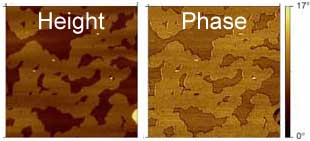
The first article is about Phase Imaging, an often misunderstood technique in AFM.
The second "modes" article is about Magnetic Force microscopy, MFM. This technique allows MFM to measure magnetic fields.

 The articles in the book all contain a full reference list.
Images in this article come from the book, and are Copyright Peter Eaton/ OUP 2010.
- Details
- Hits: 28546
There is some confusion about phase imaging. Phase imaging is not really an operation mode in itself. It is carried out in intermittent contact mode (IC-AFM). In commercial AFMs. depending on the instrument, IC-AFM may be referred to as AC-AFM, vibrating mode, tapping, etc. If you carry out IC-AFM and monitor the phase signal, you are doing what is referred to as "phase imaging", i.e. generating a phase-contrast AFM image. Further confusion can occur because of the unrelated optical microscopy technique "phase contrast microscopy". There is also a technique in TEM called "phase-contrast imaging". Even more confusingly, with heterogeneous materials samples, researchers often refer to the different materials in the sample as forming different phases. Thus, many users are confused about what phase imaging in AFM really is. However, it is a powerful technique, for producing contrast on heterogeneous samples. In this shortened extract from Atomic Force Microscopy. The origin of the signal and its use is described in this article.
- Details
- Hits: 75546
Magnetic Force Microscopy
Magnetic force microscopy (MFM), is a family of techniques used to measure magnetic fields using an AFM. In fact there are a large number of different techniques used to measure magnetic properties, but in general, they all use the AFM to measure the oscillation of a magnetically sensitive probe when it is far (5-100 nm) from the sample surface. MFM probes are usually made by coating normal silicon probes with a thin magnetic coating. The magnetic coating means that the oscillation of the probe will change when in a magnetic field. However, when the probe is touching the sample, the short range tip-sample forces will obscure the magnetic forces (which are much weaker). Fortunately, since magnetic forces can be measured at a distance, it is possible to remove the probe from the surface, and still measure magnetic forces, while removing these short range forces. In order to make accurate measurements, the probe should be at the same distance from the sample throughout the image. There are a number of techniques to do this, which are reviewed in [1], but in most commercial implementations, the so-called “Lifting” method first used by Bard [2] is used. This method is illustrated schematically below.
 How MFM lifting modes work
In order to make MFM measurements with this lifting mode, an oscillating mode is used, typically intermittent contact mode AFM. For each line of the image, two scans are made. In the first line, the topography is measured as usual. The probe is then lifted a user-defined distance above the surface (typically in the range 5 to 50 nm). The second line will then be measured, but the topography measured in the first line is added to the height of the probe as it scans along the line. In this way, the instrument attempts to keep the probe at exactly the same distance from the sample surface at each point in the MFM image. MFM is widely used to generate images of magnetic fields associated with small domains, and is particularly of use in the development of magnetic recording technology . It can also show magnetic fields associated with individual magnetic nanoparticles[3]. However, interpretation of MFM signals is complicated by the unknown nature of the probe, and it is limited to measuring fairly intense fields[4,1].
The image above shows topogrpahic (left) and magnetic field (right) images of a cluster of magnetic nanoparticles.
References
Eaton P et al. (2010) Atomic force microscopy. OUP, Oxford
Lin CW et al. (1987). J Electrochem Soc 134:1038-1039.
Neves CS et al. (2010). Nanotechnology 21:305706.
Schreiber S et al. (2008). Small 4:270-278.
This article was condensed from “Atomic Force Microscopy” by Eaton and West, OUP, 2010. The article comes from Chapter 3, which describes all of the commonly used modes in Atomic Force Microscopes. The Article in the book also contains a full reference list.
Images in this article come from the book, and are Copyright Peter Eaton/ OUP 2010.
- Details
- Hits: 30660
Subcategories
Page 13 of 21