There is some confusion about phase imaging. Phase imaging is not really an operation mode in itself. It is carried out in intermittent contact mode (IC-AFM). In commercial AFMs. depending on the instrument, IC-AFM may be referred to as AC-AFM, vibrating mode, tapping, etc. If you carry out IC-AFM and monitor the phase signal, you are doing what is referred to as "phase imaging", i.e. generating a phase-contrast AFM image. Further confusion can occur because of the unrelated optical microscopy technique "phase contrast microscopy". There is also a technique in TEM called "phase-contrast imaging". Even more confusingly, with heterogeneous materials samples, researchers often refer to the different materials in the sample as forming different phases. Thus, many users are confused about what phase imaging in AFM really is. However, it is a powerful technique, for producing contrast on heterogeneous samples. In this shortened extract from Atomic Force Microscopy. The origin of the signal and its use is described in this article. 
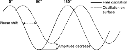
‘Phase imaging’ in AFM refers to recording the phase shift signal in intermittent-contact AFM. The phase shift can be thought of as a “delay” in the oscillation of the cantilever as is moves up and down in and out of contact with the sample, as illustrated below.

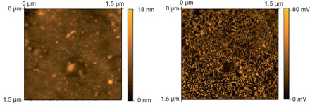
In 1995 for the first time, the phase signal was described as being sensitive to variations in composition, adhesion, friction, viscoelasticity as well as other factors. Then in 1996 Garcia and Tamayo suggested that the phase signal in soft materials is sensitive to viscoelastic properties and adhesion forces, with little participation by elastic properties. It has been a common assumption ever since that phase contrast will show adhesion or viscoelastic properties. In fact, phase contrast from material properties is seen in a wide variety of samples, but also reflects topometric differences (differences in slope). This is because the phase is really a measure of the energy dissipation involved in the contact between the tip and the sample, which depends on a number of factors, including such features as viscoelasticity, adhesion and also contact area. As contact area is dependent on the slope of the sample, the phase image also contains topographic contributions, so unambiguous interpretation of contrast in phase images is best left to flat samples. Even in such cases, understanding of the contribution of the individual factors to the phase shift is not simple. Despite the complications involved in interpretation, phase contrast is one of the most commonly used techniques for ‘mechanical’ and composition characterization of sample surfaces.
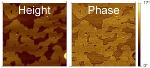
 Example of phase contrast in IC-AFM : a triblock copolymer topography (left) barely shows height differences for the different phases. The phase image (right) shows clear contrast.
 This article was condensed from “Atomic Force Microscopy” by Eaton and West, OUP, 2010. The article comes from Chapter 3, which describes all of the commonly used modes in Atomic Force Microscopes. The Article in the book also contains a full reference list.
Images in this article come from the book, and are Copyright Peter Eaton/ OUP 2010.
