Introduction
Atomic force microscopy (AFM) is a technique to obtain images and other information from a wide variety of samples, at extremely high (nanometer) resolution. AFM works by scanning a very sharp (end radius ca. 10 nm) probe along the sample surface, carefully maintaining the force between the probe and surface at a set, low level. Usually, the probe is formed by a silicon or silicon nitride cantilever with a sharp integrated tip, and the vertical bending (deflection) of the cantilever due to forces acting on the tip is detected by a laser focussed on the back of the cantilever. The laser is reflected by the cantilever onto a distant photodetector. The movement of the laser spot on the photodetector gives a greatly exaggerated measurement of the movement of the probe. This set-up is known as an optical lever. The probe is moved over the sample by a scanner, typically a piezoelectric element, which can make extremely precise movements. The combination of the sharp tip, the very sensitive optical lever, and the highly precise movements by the scanner, combined with the careful control of probe-sample forces allow the extremely high resolution of AFM.
History
AFM was a development of Scanning Tunneling Microscopy (STM)[1], intended to extend the possibilities of STM to insulating samples. The Scanning Tunneling Microscope was itself very similar to an earlier instrument called the Topografiner, invented by Young[2]. The STM, which was invented by Binnig and Rohrer[3], had much higher resolution than the topografiner, as it monitored electron tunnelling, typically from one atom at the end of a probe to a conducting substrate. However, both techniques were limited in what samples could be analyzed. Therefore, Binnig, Quate and Gerber replaced the electron tunnelling from a fine wire of the STM with the cantilever approach of AFM, which can analyze insulating samples, in 1986[1]. Commercial instruments have been available since 1988, and since then there have been many developments and new modes of operation devised for AFM.Principles of Operation
The basic principle of AFM is that a probe is maintained in close contact with the sample surface by a feedback mechanism as it scans over the surface, and the movement of the probe to stay at the same probe-sample distance is taken to be the sample topography. A variety of probes have been used but the most commonly used are microfabricated silicon (Si) or silicon nitride (Si3N4) cantilevers with integrated tips. The tips can be very sharp.Typically, probe radius varies from 5 to 20 nm. The bending of the cantilever normal to the sample surface is usually monitored by an optical lever[7], although other methods have been investigated[5]. This system magnifies the normal bending of the cantilever greatly, and is sensitive to Angstrom-level movements. There are a variety of modes of scanning (see below), but in the simplest mode, the probes gently touches the sample as it moves over the surface. The movement of the probe over the surface is controlled by a scanner. This is normally made from a piezoelectric material[8], which can move the probe very precisely in the x, y, and z axes, although other types of actuator are also used. The signal from the photodetector passes through a feedback circuit, and into the z-movement part of the scanner, in order to maintain the probe-sample distance at a set value. Because the cantilever acts as a spring[6], this fixed cantilever deflection means a fixed probe-sample force is maintained. The amount by which the scanner has to move in the z axis to maintain the cantilever deflection is taken to be equivalent to the sample topography.

A great advantage of AFM compared to for example TEM[15] or SEM, is that it is simple to operate in almost any environment, such as aqueous solutions, but also other solvents, in air, vacuum, or other gases. Depending on the details of the experiment, the resolution can be very high. z (height) resolution is extremely high and can be sub -Angstrom, whereas lateral resolution could be of the order of 1 nm. To obtain such high resolution work , the state of the sample, the levels of acoustic and electronic noise, and experimental conditions must all be highly optimised.
Operating Modes
The most commonly used modes of operation of an AFM are:
-
Contact mode AFM (aka C-AFM or CMAFM)
-
Tapping mode AFM (aka TMAFM, IC-AFM or AM-AFM)
-
Noncontact mode (aka NC-AFM, close contact AFM or FM-AFM).
Contact is often called a static mode, and Tapping and noncontact called dynamic modes, as the cantilever is oscillated in Tapping and noncontact modes. Typically this is done by adding an extra piezoelectric element that oscillates up and down at somewhere between 5-400kHz to the cantilever holder.There is a little confusion over terminology, because Tapping mode was trademarked by one AFM manufacturer, so to get around this it is known by many other names (e.g. intermittent contact (IC-AFM), ACmode, vibrating mode). Some authors prefer to refer to the modes by their detection mechanisms[9], Tapping mode would then be called Amplitude Modulation AFM (AM-AFM), and noncontact mode would be Frequency Modulation AFM (FM-AFM). The main difference between tapping mode and noncontact mode is that in tapping mode, the tip of the probe actually touches the sample, and moves completely away from the sample in each oscillation cycle. In NC-AFM, the cantilever stays close to the sample all the times, and has a much smaller oscillation amplitude. NC-AFM (noncontact AFM) is more sensitive to small oscillations of the cantilever, so may be operated in close contact (almost touching)[9]. Noncontact AFM, unlike the other AFM techniques can obtain true atomic resolution images[13]. AM-AFM is typically used for Tapping mode - where the tip actually taps the sample during each oscillation. This is often the most stable mode to use in air, and so is currently more commonly used than either noncontact or contact modes for most applications.
Nontopographic modes
Apart from the topographic modes that collect images, there are many modes designed to measure other properties of the sample. For example:- Magnetic Force Microscopy, MFM, measures the distribution of magnetic field in the sample[12].
- Kelvin Probe Microscopy (KPM) measures contact potential difference across the sample[14].
- Force Spectroscopy can measure individual molecular interactions.
- Nanoindentation can measure hardness or softness of the sample[10][11].
- Thermal modes can measure thermal parameters, for example, thermal conductivity on the nanoscale[4].
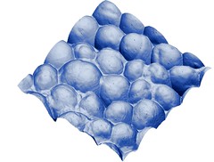
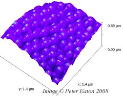
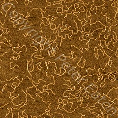
Example Images