In our lab, we have a TT-AFM, and an LS-AFM from AFM Workshop. We had one of the very first examples of this microscope, so although it's fairly new, the instrument, and the software has developed a lot during that time. On this page, I have collected together various materials that can help use the TT-AFM instrument. Note that although this material is all based on the TT-AFM, a lot of it probably applies to the other instruments from AFM Workshop, since they are all based on the same electronics. Lots of more general information about AFM operation can be found around this website (links on the left), and of course in my book.
UPDATE: The latest version of the AFM Workshop software 2.03, seems to be far superior to 1.58, which I was using previously. I reccommend strongly that everyone check this version out.
- Details
- Hits: 39769
"I really enjoyed my time on the course. In a simple and practical manner, I learned how to obtain results from AFM. I entered the course without ever being on the same lab with an AFM and left being able to carry out an experiment and analysing my own results."

The students enjoyed the course a lot, and we got lots of very positive feedback.

"I have to tell you that I'm enjoying a lot this mini-course. The language used to explain the concepts is very clear and there is a good atmosphere between all participants."
 On the first day, after meeting the students, we started with a short introduction to AFM, followed by a talk about AFM instrumentation, focussing on important concepts, and the differences between different instruments the students might encounter. Some of the students were already using AFM, and some had never used it. In fact, a couple of the students were already regular AFM users, but still found the course useful:
 "I found it useful even for people (like me) having a certain experience in the field. For instance, things that work well in/with AFM can be easily found in a lot of papers, but things that are hard or tricky to set up are seldom explicitly written in articles. The workshop addressed specifically this type of issues. Also, to my opinion, attending the workshop was not expensive at all. "
- Details
- Hits: 13950

The BIO-AFM Network is expected to be functioning in January 2014, if approved by the FCT.
In the meantime, the regulations provided here indicate that the network is already functioning on a voluntary basis, and these regulations are non-binding to the members of the network. These regulations are subject to change at any time.
Once the network is approved, these regulations will change, and the definitive version will be made available in PDF format.
1. The facilities offered are access to AFM instruments, training in AFM, especially biological applications, and support in the use of the instruments, sample preparation, and data analysis.
2. These facilities are open to all researchers, students, and industrial partners, subject to the conditions listed here.
3. Use of instruments by anyone other than BIO-AFM team members is dependent on the following points:
3.1. Probes and other consumables are provided by users, and are not part of the offer. Optionally, BIO-AFM may provide probes to users at cost price. Substrates, either muscovite mica or glass slides may also be available.
3.2. Users may only use the instruments themselves once they have proved that they have suitable training, and are competent in the use of the specific facility required.
3.3. BIO-AFM team members will provide training if necessary.
3.4. The facilities are only available during normal working hours, and there must to be other people present in the labs during working time, for security reasons.
3.5. The facilities can be booked ahead of time. At least one week is typically required. In the case of a dispute over the time allotted, the BIO-AFM management member responsible for the facility will have final say.
3.6. Cancellation of a booking must be made at least 24 hours in advance. Any fees associated to the booking will be charged if there is less notice.
4. BIO-AFM team members may also carry out experiments for facility users. This service will be charged for as specified in the regulations of the individual host institute. If prices are not otherwise specified, the BIO-AFM price list (see point 5 of this document) will be applied. This service will typically include scanning, and providing data to the user. Data analysis, and help with sample preparation may be included, at the discretion of the BIO-AFM team member.
5. Prices are revised annually for 2013-2014, they are described in: http://afmhelp.com/images/stories/AFM_Prices_2013_to_2014.pdf 6. There are three user categories.
* Scientific collaborators do not pay for use of the facilities.
* Internal users pay only consumables.
* External users pay for use by the hour, and for consumables, if required.
Registration of users as any one of the categories is at the discretion of the Lab manager, and the RI management team.
7. Access. Enquiries about access may be made either via email to This email address is being protected from spambots. You need JavaScript enabled to view it., or to the responsible member of the management team for an individual facility. Currently they are: Porto- Dr. Peter Eaton; Lisbon- Dr. Nuno Santos, Caparica- Dr. Jorge Caldeira.
- Details
- Hits: 18474

The Portuguese BIO-AFM Network is a forthcoming Research Infrastructure, or RI.
- If approved, the RI status means the network will be partially funded by FCT, and will provide open access to all who wish to become users of the RI.
- The RI will provide training, access to instrumental techniques, advice and data analysis for all users.
- This RI focusses on biological atomic force microscopy (BIO-AFM). However, use of AFM in other areas is also supported.
- The network is made up of three labs, which are based in Porto, Lisbon, and Caparica, Portugal. Information on the facilities on the three labs can be found below,and in the linked pages, describing each lab.
- At this time, the RI is in the application stage, and if approved will begin operations in January 2014. However, most of the components of the RI are already in operation, so if you want to be a users, consult the access requirements here.
- Members of the management and implementation teams are experts in many different areas of biological AFM, so if you need advice, including on whether BIO-AFM can help you, just ask! You can contact us via email This email address is being protected from spambots. You need JavaScript enabled to view it., or look at the contact details on the individual pages below.
The three labs are in:
| Porto |  |
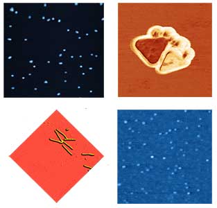
Based in DQB, Requimte Porto. This lab currently houses a TT-AFM from AFMWorkshop, with high resolution facilities. specialising in NanoBio science, bacteria and parasites. | |
| Lisbon | 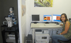 |
Based in IMM, associated to FMUL. This lab has a Nanowizard 2 from JPK, with advanced facilities for use of live cells. Specialised in force spectroscopy and biomedical applications. | |
| Caparica | 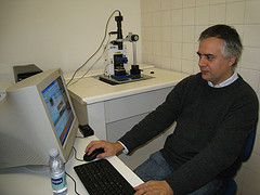 |
Based in the chemistry department, FCT-UNL. This lab houses a TT-AFM from AFMWorkshop with an experimental liquid cell for environmental work. |
Finalised regulations and conditions for access to the instruments are coming soon. In the meantime, you may consult the Draft Document. Another document contains Prices.
NEWS
- The Porto lab is currently installing a new life sciences AFM, combining optical, fluorescence and AFM measurements in one instrument.
- The Requimte AFM course for 2014 is now full, and will teach 16 students from Europe, Asia and the USA during Easter week.
- The lisbon lab at FCT-UNL has improved the microscope with a new environmental chamber. Upgrades are ongoing.
- Details
- Hits: 16105
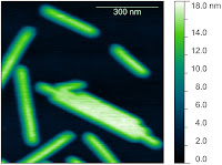
The TT-AFM is a low cost AFM that can produce reasonably high resolution images. However, the "default settings" require some tweaking in order to get high resolution images.
SCANNING SETTINGS FOR HIGH RESOLUTION
The main issue that needs to be controlled, is the use of closed or open loop operation. Closed loop operation favours highly linear scanning and measurements that can be extremely accurate, assuming calibration is done correctly. However, the noise in the sensors is too high for high resolution scanning. So, you can revert to open-loop scanning when high resolution / low noise scanning is required. In this mode, the linearity is lower, but the noise is greatly reduced, allowing for higher resolution scans. Note that this kind of compromise is required on many AFM models, not just the TT-AFM. On the other hand, some modern instruments feature position sensors with very low noise. Essentially, I recommend two sets of settings to use, a "low resolution/high noise/large scan range/high linearity" set and a ""High resolution/low noise/small scan range/low linearity" set. The difference between these settings are numbers to set in the "System" tab.
The default settings are:
| low resolution | |
| Z HV Gain | 15 |
| XY HV Gain | 15 |
| X Gain % | 100 |
| Y Gain % | 100 |
(probably your instrument was originally configured using these settings)
To get a dramtic reduction in noise, and increase in z and xy resolution use:
| high resolution | |
| Z HV Gain | 5 |
| XY HV Gain | 5 |
| X Gain % | 0 |
| Y Gain % | 0 |
NOTES:
1- IMPORTANT! Be careful when adjusting these settings, double check that you do not enter some crazy values. Assume that these fields have no "error check" routine. If you use the wrong values you may damage your instrument!
2 – IMPORTANT! I am assuming you are using v2.03 of the software, if not, the procedure will probably be different. At the time of writing v2.03 seems to be the best version.
3- These values are, I believe, saved in the scanner.cfg file, so you could set up two files, with the two sets of values to be more convenient, and avoid any errors in typing the values.
4- Reducing XY HV Gain reduces the scan size, so a Range check is ABSOLUTELY necessary. Even if it does not look like it's necessary, in general I would recommend re-doing range check, after changing any of the XY parameters.
5- The difference compared to the images you sent, should be a reduction in XY jitter at the edges of your features (tubes). Essentially, the Gain(%) values control the feedback from the XY position sensors. The signal they give is very noisy compared to the precision of the piezos, so by setting this to 0, you turn off the sensors, and remove this noise.
6-Because of point 5, the "high resolution" mode is NOT LINEAR. This may mean some XY distortion in your images, and inaccurate zooming.
7- When you reduce XY HV Gain, you reduce the range in XY. So these values above gave you reduce range by 2/3, and you end up with a range of around 16.6 um. If you want to do large scans, you could turn off the sensors, but leave HV gains alone, so you would use:
| low noise/large range | |
| Z HV Gain | 15 |
| XY HV Gain | 15 |
| X Gain % | 0 |
| Y Gain % | 0 |
8- As a side note, if you ever used another AFM, this may seem a bit fiddly, but in fact all of these settings are used in other AFM systems as well. The difference with the TT-AFM is it is manual, not done automatically. Yet. Of course, this is one reason why the instrument works out at such a low price!
TIP APPROACH FOR HIGH RESOLUTION
If you use the settings above for the first time, you may notice a drastic improvement in noise level. Then you may well start to see other issues become apparent. For one, you may be able to see whether your vibration/acoustic noise isolation system really works or not! Another issue is probe tip size.
In all AFMs, the achieved resolution is controlled by the size of the probe tip WHILE SCANNING. That means, not the size of the tip in the box, but on the sample. What happens between the probe being nice and sharp in your box, and scanning your sample? Tip Approach! Good tip approach is crucial for high resolution scanning. Below I include two tips to improve the chance of beginning your san with a sharp probe:
1. Use conservative tip approach parameters. By conservative, I mean a slow, well-controlled tip approach, which does not result in a low set point. By default, your system probably came with tip approach parameters that guarantee a successful approach every time, but also pretty much guarantee you will not have a sharp probe after approach. Again, I am assuming you are using V2.03 of the software. The tip approach routine is completely different in some other versions of the software. Look at the collection of controls in the System Tab, labelled “Tip approach parameters”, highlighted below.
Note that these parameters are considered “Advanced Controls” by the AFM Workshop Software. They may therefore be hidden. There is a grey button on the Pre-Scan tab (location highlighted below) that makes these control appear and disappear.
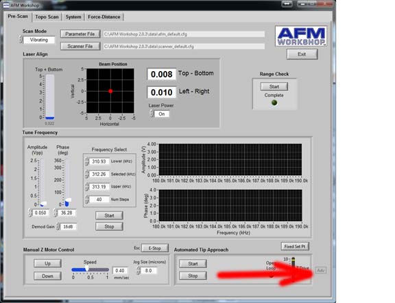
Incidentally, just above here, is a control that swaps between “Update Setpoint” and “Fixed Setpoint” Ensure this is set to “Update Setpoint” EVERY TIME you approach.
There are two things I recommend you can change in the tip approach parameters to enable a conservative approach. Firstly, and most importantly, you should adjust the value labelled “extend factor” to reflect the setpoint upon approach. This is a fraction of the free amplitude, which is used to detect approach. Lower values will lead to a lower setpoint (vibrating mode). So, lower values will be less prone to false feedback, but more prone to blunting your probe. I recommend you experiment with values between 0.91 and 0.94.
2. There is a bug in the software which might cause rather rapid translation when the scan region moves one place to another. Essentially, after range check, if you request a scan in the centre of the scan range, the probe will move very quickly to your requested spot, which could lead to probe damage. To avoid this (especially when you have a new probe, and want high resolution). Before any tip approach, set the scan center and scan range to your desired initial values, and begin a scan BEFORE approach. Allow the software to collect one scan line (it should be empty), then stop the scan. Now approach, and start scanning. In this way, translation to the initial scan position is minimised.
As always, please contact me with any comments on this article. All content copyright 2013 Peter Eaton.
- Details
- Hits: 29027
Subcategories
Page 16 of 21